Working with Rotary Encoders
A rotary encoder is a digital rotary sensor. It has the capability of rotating 360 degrees and can tell you direction. This tutorial is based on Paul Stoffregen’s Encoder library and explanations.
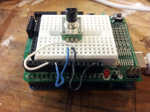
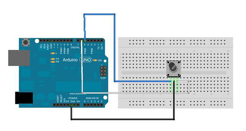
Inside of a rotary encoder are 2 contacts that are read by the arduino and the center contact grounds the encoder. The rotary encoder has a built in pattern that helps determine the direction you are spinning. The rotary encoder is essentially 2 switches. When Pin 1 goes high you are moving left. When Pin 2 goes high you are going right.
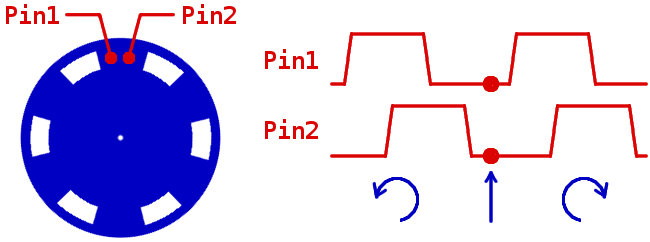
Pin 1 == Low & Pin 2 == Low ==> Position 1
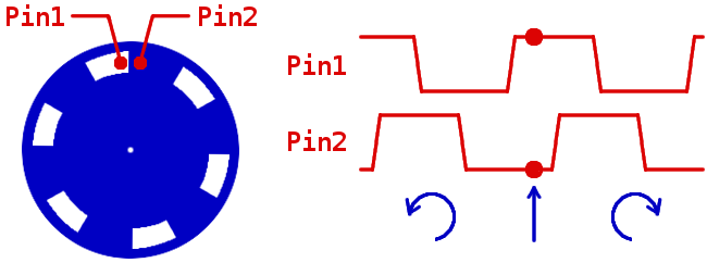
Pin 1 == High & Pin 2 == Low ==> Position 2. Â We know that we have moved left.
The arduino pins read the  HIGH and LOW of the pins to determine the direction. To simplify this process we are using this library http://www.pjrc.com/teensy/td_libs_Encoder.html. I used the basic code in the library example.
Arduino
[cc lang=”c”]
/* Encoder Library – Basic Example
- http://www.pjrc.com/teensy/td_libs_Encoder.html
This example code is in the public domain.
*/
#include
Advanced Topic: Inverse Logic and Arduino Pull-up
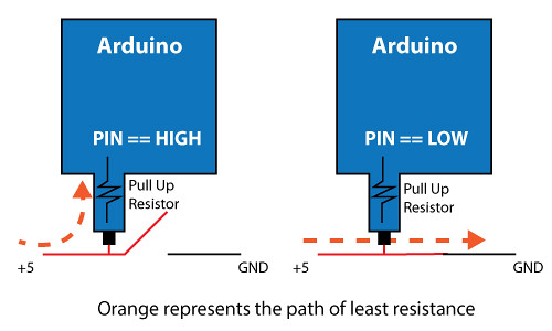
The Rotary Encoder is essentially 2 switches. This library sets both pins as INPUTS, followed by setting a digitalWrite to HIGH. This engages the arduino’s pull-up resistor for that pin. What the pull-up resistor does it allows a small trickle of positive voltage into the pin. Setting that pin to constantly read HIGH until you rotate the knob where the state would change to LOW. We normally think in HIGH being On and LOW being Off. With Inverse Logic HIGH is your Off state and LOW is your On state. In the case of the rotary encoder, when the pin makes contact with the white area, the encoder makes a connection to ground. Ground is now the path of lease resistance. So no electricity is flowing through the pull-up resistor, thus the pin goes Low. The orange represents the path of least resistance and the flow of electricity.
Note: This library can use the arduino interrupt pins for better performance.